

How To Find The Current Through A Resistor
10.iii: Resistors in Serial and Parallel
- Page ID
- 4408
Learning Objectives
By the end of the section, you lot volition be able to:
- Define the term equivalent resistance
- Calculate the equivalent resistance of resistors continued in series
- Calculate the equivalent resistance of resistors continued in parallel
In Current and Resistance, we described the term 'resistance' and explained the bones blueprint of a resistor. Basically, a resistor limits the flow of charge in a circuit and is an ohmic device where \(V = IR\). Nearly circuits have more than i resistor. If several resistors are connected together and continued to a bombardment, the current supplied by the bombardment depends on the equivalent resistance of the circuit.
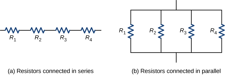
The equivalent resistance of a combination of resistors depends on both their private values and how they are connected. The simplest combinations of resistors are series and parallel connections (Figure \(\PageIndex{1}\)). In a series circuit , the output current of the start resistor flows into the input of the 2nd resistor; therefore, the electric current is the same in each resistor. In a parallel circuit , all of the resistor leads on one side of the resistors are connected together and all the leads on the other side are connected together. In the case of a parallel configuration, each resistor has the aforementioned potential driblet across it, and the currents through each resistor may be different, depending on the resistor. The sum of the private currents equals the current that flows into the parallel connections.
Resistors in Series
Resistors are said to exist in series whenever the current flows through the resistors sequentially. Consider Figure \(\PageIndex{two}\), which shows three resistors in serial with an applied voltage equal to \(V_{ab}\). Since at that place is only one path for the charges to flow through, the electric current is the same through each resistor. The equivalent resistance of a set of resistors in a series connection is equal to the algebraic sum of the individual resistances.
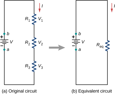
In Effigy \(\PageIndex{2}\), the current coming from the voltage source flows through each resistor, so the current through each resistor is the same. The current through the circuit depends on the voltage supplied by the voltage source and the resistance of the resistors. For each resistor, a potential drop occurs that is equal to the loss of electric potential energy as a current travels through each resistor. According to Ohm'southward police force, the potential drop \(V\) across a resistor when a current flows through it is calculated using the equation \(V = IR\), where \(I\) is the current in amps (\(A\)) and \(R\) is the resistance in ohms \((\Omega)\). Since energy is conserved, and the voltage is equal to the potential energy per charge, the sum of the voltage applied to the circuit by the source and the potential drops across the individual resistors around a loop should be equal to zero:
\[\sum_{i = one}^Northward V_i = 0.\]
This equation is oft referred to as Kirchhoff'due south loop law, which we volition look at in more detail later in this chapter. For Figure \(\PageIndex{two}\), the sum of the potential drop of each resistor and the voltage supplied past the voltage source should equal zero:
\[\brainstorm{align*} V - V_1 - V_2 - V_3 &= 0, \\[4pt] V &= V_1 + V_2 + V_3, \\[4pt] &= IR_1 + IR_2 + IR_3, \stop{align*}\]
Solving for \(I\)
\[\begin{align*} I &= \frac{V}{R_1 + R_2 + R_3} \\[4pt] &= \frac{V}{R_{S}}. \end{align*}\]
Since the current through each component is the aforementioned, the equality can be simplified to an equivalent resistance (\(R_{Due south}\)), which is merely the sum of the resistances of the individual resistors.
Equivalent Resistance in Series Circuits
Any number of resistors tin be connected in series. If \(N\) resistors are connected in series, the equivalent resistance is
\[R_{S} = R_1 + R_2 + R_3 + . . . + R_{Due north-1} + R_N = \sum_{i=1}^N R_i. \label{equivalent resistance series}\]
One event of components connected in a series circuit is that if something happens to i component, it affects all the other components. For example, if several lamps are continued in series and one bulb burns out, all the other lamps go night.
Example \(\PageIndex{1}\): Equivalent Resistance, Current, and Power in a Series Circuit
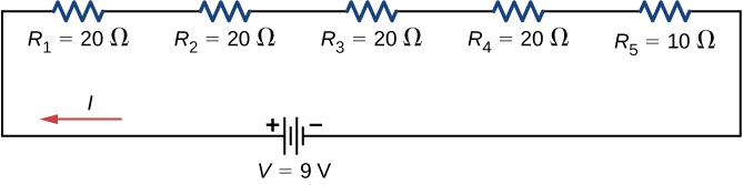
A battery with a concluding voltage of 9 5 is connected to a circuit consisting of 4 \(20 \, \Omega\) and one \(10 \, \Omega\) resistors all in series (Figure \(\PageIndex{3}\)). Assume the bombardment has negligible internal resistance.
- Calculate the equivalent resistance of the circuit.
- Calculate the current through each resistor.
- Summate the potential drop across each resistor.
- Make up one's mind the total power prodigal by the resistors and the power supplied by the bombardment.
Strategy
In a serial circuit, the equivalent resistance is the algebraic sum of the resistances. The current through the circuit can be found from Ohm'south constabulary and is equal to the voltage divided by the equivalent resistance. The potential drib across each resistor can be establish using Ohm's law. The ability dissipated by each resistor can be found using \(P = I^2R\), and the total ability prodigal by the resistors is equal to the sum of the ability prodigal by each resistor. The power supplied by the battery tin can be establish using \(P = I\epsilon\).
Solution
- The equivalent resistance is the algebraic sum of the resistances (Equation \ref{equivalent resistance series}): \[\begin{marshal*} R_{South} &= R_1 + R_2 + R_3 + R_4 + R_5 \\[4pt] &= xx \, \Omega + 20 \, \Omega + twenty \, \Omega + 20 \, \Omega + 10 \, \Omega = xc \, \Omega. \end{marshal*}\]
- The current through the circuit is the aforementioned for each resistor in a series excursion and is equal to the applied voltage divided by the equivalent resistance: \[I = \frac{V}{R_{Southward}} = \frac{9 \, Five}{90 \, \Omega} = 0.1 \, A. \nonumber\] Annotation that the sum of the potential drops beyond each resistor is equal to the voltage supplied by the battery.
- The ability dissipated by a resistor is equal to \(P = I^2R\), and the power supplied by the battery is equal to \(P = I\epsilon\). \[P_1 = P_2 = P_3 = P_4 = (0.ane \, A)^2 (20 \, \Omega) = 0.2 \, Due west,\nonumber\] \[P_5 = (0.1 \, A)^2 (10 \, \Omega) = 0.one \, West,\nonumber\] \[P_{dissipated} = 0.2 \, Due west + 0.2 \, W + 0.2 \, W + 0.2 \, W + 0.1 \, W = 0.9 \, W,\nonumber\] \[P_{source} = I\epsilon = (0.ane \, A)(ix \, V) = 0.9 \, Due west. \nonumber\]
Significance
There are several reasons why we would utilise multiple resistors instead of just one resistor with a resistance equal to the equivalent resistance of the excursion. Perhaps a resistor of the required size is not available, or we demand to dissipate the heat generated, or nosotros desire to minimize the cost of resistors. Each resistor may cost a few cents to a few dollars, simply when multiplied by thousands of units, the price saving may be appreciable.
Practice \(\PageIndex{i}\)
Some strings of miniature holiday lights are made to short out when a seedling burns out. The device that causes the short is called a shunt, which allows current to menstruum around the open circuit. A "brusque" is like putting a piece of wire across the component. The bulbs are usually grouped in series of ix bulbs. If too many bulbs burn out, the shunts eventually open up. What causes this?
- Answer
-
The equivalent resistance of 9 bulbs connected in series is 9R. The current is \(I = Five/9 \, R\). If one seedling burns out, the equivalent resistance is 8R, and the voltage does non change, but the current increases \((I = 5/viii \, R\). As more than bulbs fire out, the current becomes fifty-fifty college. Eventually, the current becomes as well high, burning out the shunt.
Let's briefly summarize the major features of resistors in series:
- Series resistances add together together to go the equivalent resistance (Equation \ref{equivalent resistance series}): \[R_{S} = R_1 + R_2 + R_3 + . . . + R_{N-1} + R_N = \sum_{i=1}^N R_i.\]
- The same current flows through each resistor in series.
- Private resistors in series exercise non get the total source voltage, but divide it. The total potential driblet across a series configuration of resistors is equal to the sum of the potential drops across each resistor.
Resistors in Parallel
Figure \(\PageIndex{four}\) shows resistors in parallel, wired to a voltage source. Resistors are in parallel when ane end of all the resistors are connected by a continuous wire of negligible resistance and the other finish of all the resistors are also connected to one some other through a continuous wire of negligible resistance. The potential drop across each resistor is the same. Electric current through each resistor can be institute using Ohm's law \(I = Five/R\), where the voltage is constant across each resistor. For instance, an automobile's headlights, radio, and other systems are wired in parallel, and then that each subsystem utilizes the full voltage of the source and can operate completely independently. The same is true of the wiring in your house or any edifice.
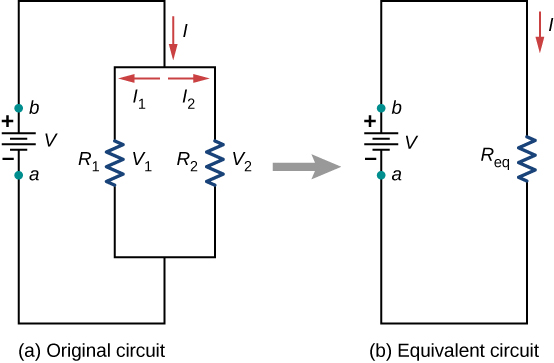
The current flowing from the voltage source in Figure \(\PageIndex{4}\) depends on the voltage supplied past the voltage source and the equivalent resistance of the circuit. In this case, the current flows from the voltage source and enters a junction, or node, where the circuit splits flowing through resistors \(R_1\) and \(R_2\). Every bit the charges catamenia from the bombardment, some get through resistor \(R_1\) and some menses through resistor \(R_2\). The sum of the currents flowing into a junction must exist equal to the sum of the currents flowing out of the junction:
\[\sum I_{in} = \sum I_{out}. \nonumber\]
This equation is referred to as Kirchhoff'south junction dominion and will be discussed in particular in the next section. In Figure \(\PageIndex{4}\), the junction dominion gives \(I = I_1 + I_2\). There are two loops in this circuit, which leads to the equations \(V = I_1R_1\) and \(I_1R_1 = I_2R_2\). Annotation the voltage across the resistors in parallel are the same ( \(Five = V_1 = V_2\)) and the electric current is additive:
\[ \begin{marshal*} I &= I_1 + I_2 \\[4pt] &= \frac{V_1}{R_1} + \frac{V_2}{R_2} \\[4pt] &= \frac{5}{R_1} + \frac{Five}{R_2} \\[4pt] &= 5 \left( \frac{i}{R_1} + \frac{1}{R_2} \right) = \frac{5}{R_{P}}\end{align*}\]
Solving for the \(R_{P}\)
\[R_{P} = \left(\frac{1}{R_1} + \frac{ane}{R_2} \right)^{-i}. \]
Equivalent Resistance in Parallel Circuits
Generalizing to any number of \(N\) resistors, the equivalent resistance \(R_{P}\) of a parallel connection is related to the individual resistances by
\[R_{P} = \left( \frac{1}{R_1} + \frac{ane}{R_2} + \frac{1}{R_3} + . . . + \frac{1}{R_{N-one}} + \frac{1}{R_N} \right)^{-1} = \left(\sum_{i=1}^Due north \frac{ane}{R_i} \right)^{-1}. \label{ten.3}\]
This human relationship results in an equivalent resistance \(R_{P}\) that is less than the smallest of the individual resistances. When resistors are connected in parallel, more current flows from the source than would flow for any of them individually, so the total resistance is lower.
Case \(\PageIndex{2}\): Analysis of a parallel circuit
Three resistors \(R_1 = 1.00 \, \Omega\), \(R_2 = 2.00 \, \Omega\), and \(R_3 = 2.00 \, \Omega\), are connected in parallel. The parallel connection is attached to a \(V = three.00 \, 5\) voltage source.
- What is the equivalent resistance?
- Detect the current supplied by the source to the parallel circuit.
- Calculate the currents in each resistor and show that these add together to equal the current output of the source.
- Calculate the ability prodigal by each resistor.
- Find the power output of the source and show that it equals the total ability dissipated by the resistors.
Strategy
(a) The total resistance for a parallel combination of resistors is found using Equation \ref{10.3}. (Note that in these calculations, each intermediate answer is shown with an extra digit.)
(b) The current supplied by the source can be found from Ohm'southward law, substituting \(R_{P}\) for the total resistance \(I = \frac{V}{R_{P}}\).
(c) The individual currents are easily calculated from Ohm's law \(\left(I_i = \frac{V_i}{R_i}\right)\), since each resistor gets the total voltage. The full current is the sum of the individual currents: \[I = \sum_i I_i. \nonumber\]
(d) The power dissipated past each resistor tin can exist found using any of the equations relating power to electric current, voltage, and resistance, since all 3 are known. Let united states of america use \(P_i = V^2 /R_i\), since each resistor gets full voltage.
(e) The total power can also be calculated in several ways, utilize \(P = IV\).
Solution
- The total resistance for a parallel combination of resistors is institute using Equation \ref{ten.3}. Inbound known values gives \[R_{P} = \left( \frac{1}{R_1} + \frac{one}{R_2} + \frac{ane}{R_3} \correct)^{-1} = \left(\frac{1}{1.00 \, \Omega} + \frac{1}{2.00 \, \Omega} + \frac{1}{2.00 \, \Omega} \right)^{-1} = 0.50 \, \Omega.\nonumber\] The total resistance with the correct number of meaning digits is \(R_{eq} = 0.50 \, \Omega\). As predicted, \(R_{P}\) is less than the smallest individual resistance.
- The full current tin can exist found from Ohm'south law, substituting \(R_{P}\) for the total resistance. This gives \[I = \frac{V}{R_{P}} = \frac{three.00 \, V}{0.50 \, \Omega} = six.00 \, A.\nonumber\] Current I for each device is much larger than for the aforementioned devices connected in series (run into the previous example). A circuit with parallel connections has a smaller total resistance than the resistors connected in series.
- The individual currents are easily calculated from Ohm's constabulary, since each resistor gets the total voltage. Thus, \[I_1 = \frac{V}{R_1} = \frac{three.00 \, Five}{1.00 \, \Omega} = 3.00 \, A.\nonumber\] Similarly, \[I_2 = \frac{V}{R_2} = \frac{three.00 \, V}{2.00 \, \Omega} = 1.50 \, A\nonumber\] and \[I_3 = \frac{V}{R_3} = \frac{iii.00 \, V}{2.00 \, \Omega} = 1.50 \, A.\nonumber\] The total current is the sum of the individual currents: \[I_1 + I_2 + I_3 = 6.00 \, A.\nonumber\]
- The ability dissipated by each resistor can be institute using any of the equations relating ability to current, voltage, and resistance, since all three are known. Allow us utilise \(P = 5^2 /R\), since each resistor gets full voltage. Thus, \[P_1 = \frac{V^2}{R_1} = \frac{(3.00 \, V)^two}{1.00 \, \Omega} = 9.00 \, W.\nonumber\] Similarly, \[P_2 = \frac{5^2}{R_2} = \frac{(3.00 \, V)^two}{2.00 \, \Omega} = iv.l \, West.\nonumber\] and \[P_3 = \frac{Five^2}{R_3} = \frac{(3.00 \, Five)^2}{2.00 \, \Omega} = 4.50 \, W.\nonumber\]
- The full power can also be calculated in several ways. Choosing \(P = Iv\) and entering the full current yields \[P = 4 = (six.00 \, A)(3.00 \, V) = eighteen.00 \, W.\nonumber\]
Significance
Total power dissipated past the resistors is also eighteen.00 Westward:
\[P_1 + P_2 + P_3 = ix.00 \, Westward + 4.50 \, W + 4.50 \, W = 18.00 \, Due west.\nonumber\]
Find that the total ability dissipated by the resistors equals the power supplied by the source.
Exercise \(\PageIndex{2A}\)
Consider the same potential divergence \((5 = 3.00 \, V)\) applied to the same three resistors continued in series. Would the equivalent resistance of the series circuit be college, lower, or equal to the three resistor in parallel? Would the current through the series excursion be higher, lower, or equal to the current provided by the aforementioned voltage practical to the parallel circuit? How would the power dissipated by the resistor in series compare to the power dissipated by the resistors in parallel?
- Solution
-
The equivalent of the series circuit would exist \(R_{eq} = ane.00 \, \Omega + ii.00 \, \Omega + ii.00 \, \Omega = five.00 \, \Omega\), which is college than the equivalent resistance of the parallel circuit \(R_{eq} = 0.50 \, \Omega\). The equivalent resistor of any number of resistors is always higher than the equivalent resistance of the same resistors connected in parallel. The current through for the serial excursion would be \(I = \frac{three.00 \, V}{v.00 \, \Omega} = 0.60 \, A\), which is lower than the sum of the currents through each resistor in the parallel circuit, \(I = 6.00 \, A\). This is not surprising since the equivalent resistance of the series excursion is college. The current through a series connexion of any number of resistors will always be lower than the electric current into a parallel connection of the same resistors, since the equivalent resistance of the series circuit will be higher than the parallel circuit. The power dissipated past the resistors in series would be \(P = ane.800 \, W\), which is lower than the power dissipated in the parallel circuit \(P = eighteen.00 \, W\).
Exercise \(\PageIndex{2B}\)
How would you use a river and two waterfalls to model a parallel configuration of two resistors? How does this analogy break downwardly?
- Solution
-
A river, flowing horizontally at a constant rate, splits in two and flows over ii waterfalls. The water molecules are analogous to the electrons in the parallel circuits. The number of water molecules that flow in the river and falls must be equal to the number of molecules that flow over each waterfall, just like sum of the current through each resistor must be equal to the electric current flowing into the parallel circuit. The h2o molecules in the river have energy due to their move and summit. The potential energy of the water molecules in the river is constant due to their equal heights. This is analogous to the constant alter in voltage across a parallel excursion. Voltage is the potential energy across each resistor.
The analogy chop-chop breaks down when considering the energy. In the waterfall, the potential energy is converted into kinetic energy of the h2o molecules. In the example of electrons flowing through a resistor, the potential drib is converted into estrus and light, not into the kinetic energy of the electrons.
Let us summarize the major features of resistors in parallel:
- Equivalent resistance is constitute from Equation \ref{10.3} and is smaller than any individual resistance in the combination.
- The potential drop across each resistor in parallel is the aforementioned.
- Parallel resistors do not each get the full electric current; they divide it. The current entering a parallel combination of resistors is equal to the sum of the current through each resistor in parallel.
In this chapter, we introduced the equivalent resistance of resistors connect in series and resistors connected in parallel. Y'all may recall from the Department on Capacitance, we introduced the equivalent capacitance of capacitors connected in series and parallel. Circuits often contain both capacitors and resistors. Table \(\PageIndex{i}\) summarizes the equations used for the equivalent resistance and equivalent capacitance for serial and parallel connections.
| Serial combination | Parallel combination | |
|---|---|---|
| Equivalent capacitance | \[\frac{ane}{C_{Southward} }= \frac{1}{C_1} + \frac{1}{C_2} + \frac{one}{C_3} + . . . \nonumber\] | \[C_{P} = C_1 + C_2 + C_3 + . . . \nonumber\] |
| Equivalent resistance | \[R_{S} = R_1 + R_2 + R_3 + . . . = \sum_{i=1}^N R_i \nonumber\] | \[\frac{1}{R_{P}} = \frac{1}{R_1} + \frac{1}{R_2} + \frac{1}{R_3} + . . . \nonumber\] |
Combinations of Series and Parallel
More complex connections of resistors are oft but combinations of series and parallel connections. Such combinations are common, peculiarly when wire resistance is considered. In that example, wire resistance is in series with other resistances that are in parallel.
Combinations of serial and parallel can be reduced to a single equivalent resistance using the technique illustrated in Figure \(\PageIndex{5}\). Diverse parts can be identified as either serial or parallel connections, reduced to their equivalent resistances, and and then further reduced until a unmarried equivalent resistance is left. The process is more than time consuming than difficult. Here, we notation the equivalent resistance as \(R_{eq}\).
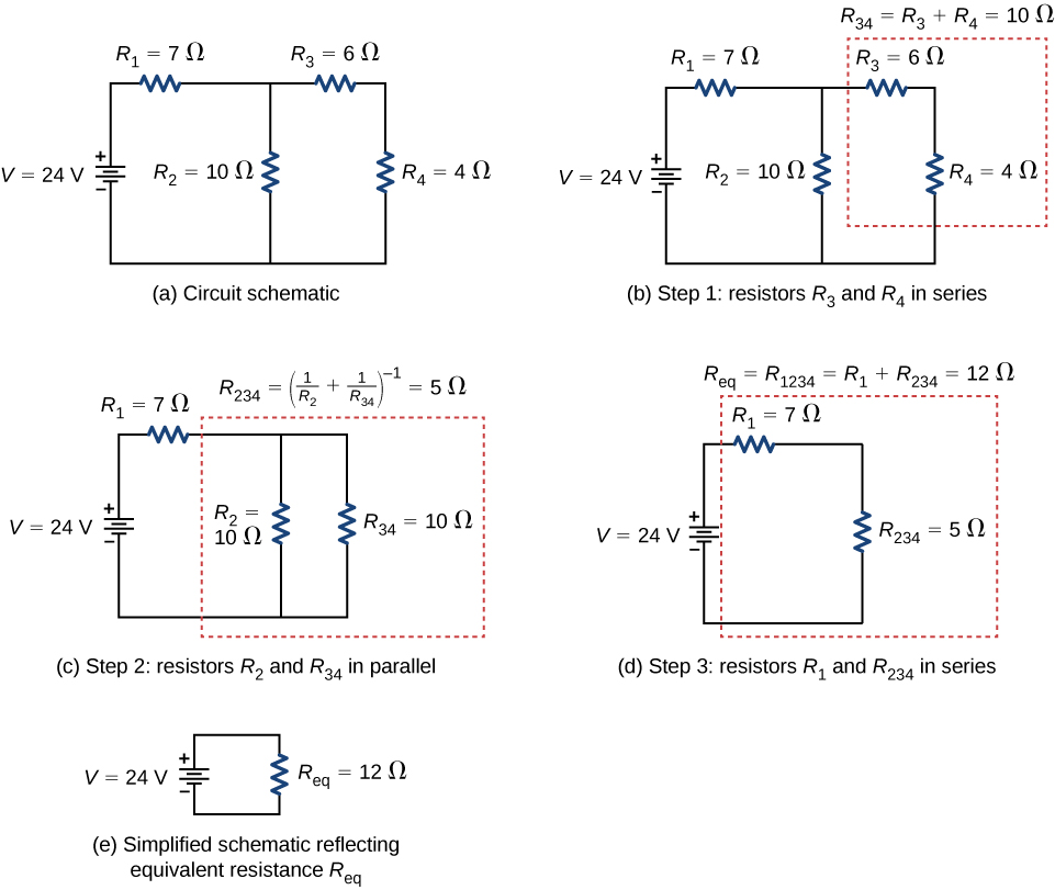
Notice that resistors \(R_3\) and \(R_4\) are in serial. They can be combined into a single equivalent resistance. One method of keeping track of the process is to include the resistors as subscripts. Hither the equivalent resistance of \(R_3\) and \(R_4\) is
\[R_{34} = R_3 + R_4 = 6 \, \Omega + 4 \, \Omega = x \, \Omega. \nonumber\]
The excursion now reduces to three resistors, shown in Effigy \(\PageIndex{5c}\). Redrawing, we now see that resistors \(R_2\) and \(R_{34}\) plant a parallel excursion. Those two resistors tin can be reduced to an equivalent resistance:
\[R_{234} = \left( \frac{ane}{R_2} + \frac{1}{R_{34}}\right)^{-ane} = \left(\frac{1}{x \, \Omega} + \frac{1}{10 \, \Omega} \right)^{-1} = 5 \, \Omega. \nonumber\]
This step of the process reduces the circuit to two resistors, shown in in Effigy \(\PageIndex{5d}\). Here, the circuit reduces to two resistors, which in this example are in series. These 2 resistors tin be reduced to an equivalent resistance, which is the equivalent resistance of the circuit:
\[R_{eq} = R_{1234} = R_1 + R_{234} = seven \, \Omega + v \Omega = 12 \, \Omega. \nonumber\]
The main goal of this circuit analysis is reached, and the circuit is now reduced to a unmarried resistor and single voltage source.
Now nosotros can analyze the excursion. The electric current provided by the voltage source is \(I = \frac{V}{R_{eq}} = \frac{24 \, V}{12 \, \Omega} = two \, A\). This current runs through resistor \(R_1\) and is designated as \(I_1\). The potential drib across \(R_1\) can exist plant using Ohm'south police force:
\[V_1 = I_1R_1 = (2 \, A)(7 \, \Omega) = xiv \, V. \nonumber\]
Looking at Figure \(\PageIndex{5c}\), this leaves \(24 \, V - 14 \, V = 10 \, 5\) to be dropped beyond the parallel combination of \(R_2\) and \(R_{34}\). The electric current through \(R_2\) can be found using Ohm's law:
\[I_2 = \frac{V_2}{R_2} = \frac{10 \, V}{10 \, \Omega} = 1 \, A. \nonumber\]
The resistors \(R_3\) and \(R_4\) are in serial then the currents \(I_3\) and \(I_4\) are equal to
\[I_3 = I_4 = I - I_2 = 2 \, A - 1 \, A = 1 \, A. \nonumber\]
Using Ohm's law, nosotros can find the potential drop beyond the last 2 resistors. The potential drops are \(V_3 = I_3R_3 = 6 \, V\) and \(V_4 = I_4R_4 = four \, Five\). The final analysis is to await at the power supplied by the voltage source and the power dissipated by the resistors. The power dissipated by the resistors is
\[\begin{marshal*}P_1 &= I_1^2R_1 = (2 \, A)^2 (7 \, \Omega) = 28 \, Westward, \\[4pt] P_2 &= I_2^2R_2 = (1 \, A)^2 (10 \, \Omega) = 10 \, W, \\[4pt] P_3 &= I_3^2R_3 = (1 \, A)^2 (6 \, \Omega) = vi \, Westward, \\[4pt] P_4 &= I_4^2R_4 = (1 \, A)^ii (4 \, \Omega) = 4 \, W, \\[4pt] P_{dissipated} &= P_1 + P_2 + P_3 + P_4 = 48 \, W. \stop{align*}\]
The total free energy is constant in any process. Therefore, the power supplied by the voltage source is
\[\begin{align*} P_s &= 4 \\[4pt] &= (2 \, A)(24 \, V) = 48 \, West \end{marshal*}\]
Analyzing the power supplied to the circuit and the power prodigal past the resistors is a good check for the validity of the assay; they should be equal.
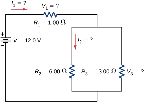
Instance \(\PageIndex{3}\): Combining Serial and parallel circuits
Effigy \(\PageIndex{6}\) shows resistors wired in a combination of serial and parallel. We tin can consider \(R_1\) to be the resistance of wires leading to \(R_2\) and \(R_3\).
- Find the equivalent resistance of the circuit.
- What is the potential drop \(V_1\) beyond resistor \(R_1\)?
- Find the electric current \(I_2\) through resistor \(R_2\).
- What ability is prodigal by \(R_2\)?
Strategy
(a) To notice the equivalent resistance, first find the equivalent resistance of the parallel connection of \(R_2\) and \(R_3\). Then employ this event to notice the equivalent resistance of the serial connection with \(R_1\).
(b) The electric current through \(R_1\) can exist found using Ohm's law and the voltage applied. The electric current through \(R_1\) is equal to the current from the battery. The potential drop \(V_1\) across the resistor \(R_1\) (which represents the resistance in the connecting wires) tin exist found using Ohm's law.
(c) The current through \(R_2\) can be found using Ohm's police force \(I_2 = \frac{V_2}{R_2}\). The voltage across \(R_2\) tin exist found using \(V_2 = V - V_1\).
(d) Using Ohm'south police \((V_2 = I_2R_2)\), the power dissipated by the resistor can also be institute using \(P_2 = I_2^2 R_2 = \frac{V_2^2}{R_2}\).
Solution
- To notice the equivalent resistance of the circuit, notice that the parallel connection of \(R_2\) and \(R_3\) is in series with \(R_1\), so the equivalent resistance is \[R_{eq} = R_1 + \left(\frac{ane}{R_2} + \frac{ane}{R_3} \right)^{-1} = one.00 \, \Omega + \left(\frac{ane}{6.00 \, \Omega} + \frac{1}{13.00 \, \Omega}\right)^{-one} = 5.10 \, \Omega.\nonumber\] The total resistance of this combination is intermediate betwixt the pure series and pure parallel values (\(twenty.0 \, \Omega\) and \(0.804 \, \Omega\), respectively).
- The electric current through \(R_1\) is equal to the electric current supplied by the battery: \[I_1 = I = \frac{V}{R_{eq}} = \frac{12.0 \, 5}{5.10 \, \Omega} = 2.35 \, A.\nonumber\] The voltage across \(R_1\) is \[V_1 = I_1R_1 = (ii.35 \, A)(1 \, \Omega) = 2.35 \, V.\nonumber\] The voltage practical to \(R_2\) and \(R_3\) is less than the voltage supplied by the battery by an amount \(V_1\). When wire resistance is large, it can significantly bear on the operation of the devices represented by \(R_2\) and \(R_3\).
- To find the current through \(R_2\), we must first find the voltage practical to information technology. The voltage across the ii resistors in parallel is the same: \[V_2 = V_3 = Five - V_1 = 12.0 \, V - ii.35 \, V = ix.65 \, Five.\nonumber\] At present we can detect the current \(I_2\) through resistance \(R_2\) using Ohm's law: \[I_2 = \frac{V_2}{R_2} = \frac{9.65 \, Five}{half-dozen.00 \, \Omega} = 1.61 \, A.\nonumber\] The current is less than the two.00 A that flowed through \(R_2\) when information technology was connected in parallel to the bombardment in the previous parallel circuit case.
- The ability dissipated by \(R_2\) is given past \[P_2 = I_2^2R_2 = (1.61 \, A)^2 (six.00 \, \Omega) = 15.five \, W. \nonumber\]
Significance
The analysis of circuitous circuits tin can often be simplified by reducing the circuit to a voltage source and an equivalent resistance. Even if the entire excursion cannot be reduced to a single voltage source and a single equivalent resistance, portions of the circuit may be reduced, profoundly simplifying the assay.
Exercise \(\PageIndex{iii}\)
Consider the electrical circuits in your dwelling. Give at least two examples of circuits that must utilise a combination of serial and parallel circuits to operate efficiently.
- Solution
-
All the overhead lighting circuits are in parallel and connected to the chief supply line, so when 1 bulb burns out, all the overhead lighting does not become dark. Each overhead light will have at least one switch in series with the low-cal, so you can turn it on and off.
A refrigerator has a compressor and a light that goes on when the door opens. There is unremarkably just one cord for the fridge to plug into the wall. The circuit containing the compressor and the circuit containing the lighting circuit are in parallel, merely there is a switch in serial with the light. A thermostat controls a switch that is in series with the compressor to control the temperature of the fridge.
Practical Implications
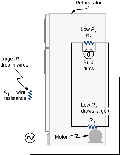
I implication of this concluding example is that resistance in wires reduces the current and power delivered to a resistor. If wire resistance is relatively large, as in a worn (or a very long) extension string, and then this loss tin exist meaning. If a large electric current is fatigued, the IR driblet in the wires tin can also be pregnant and may become apparent from the oestrus generated in the string.
For example, when you lot are rummaging in the refrigerator and the motor comes on, the refrigerator light dims momentarily. Similarly, you can see the passenger compartment light dim when you lot kickoff the engine of your car (although this may exist due to resistance inside the battery itself).
What is happening in these high-current situations is illustrated in Figure \(\PageIndex{seven}\). The device represented by \(R_3\) has a very depression resistance, so when information technology is switched on, a large current flows. This increased current causes a larger IR drop in the wires represented by \(R_1\), reducing the voltage beyond the light bulb (which is \(R_2\)), which then dims noticeably.
Trouble-Solving Strategy: Serial and Parallel Resistors
- Depict a clear circuit diagram, labeling all resistors and voltage sources. This step includes a list of the known values for the trouble, since they are labeled in your circuit diagram.
- Place exactly what needs to be determined in the problem (identify the unknowns). A written listing is useful.
- Determine whether resistors are in series, parallel, or a combination of both series and parallel. Examine the excursion diagram to make this assessment. Resistors are in serial if the aforementioned current must pass sequentially through them.
- Apply the appropriate list of major features for series or parallel connections to solve for the unknowns. At that place is 1 list for series and another for parallel.
- Bank check to see whether the answers are reasonable and consequent.
Instance \(\PageIndex{four}\): Combining Serial and Parallel circuits
Two resistors connected in series \((R_1, \, R_2)\) are continued to two resistors that are connected in parallel \((R_3, \, R_4)\). The series-parallel combination is connected to a battery. Each resistor has a resistance of x.00 Ohms. The wires connecting the resistors and battery accept negligible resistance. A current of 2.00 Amps runs through resistor \(R_1\). What is the voltage supplied past the voltage source?
Strategy
Use the steps in the preceding problem-solving strategy to find the solution for this case.
Solution
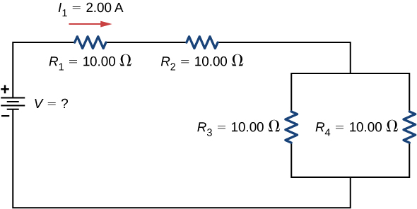
- Draw a clear circuit diagram (Figure \(\PageIndex{viii}\)).
- The unknown is the voltage of the battery. In order to find the voltage supplied past the battery, the equivalent resistance must be institute.
- In this circuit, we already know that the resistors \(R_1\) and \(R_2\) are in series and the resistors \(R_3\) and \(R_4\) are in parallel. The equivalent resistance of the parallel configuration of the resistors \(R_3\) and \(R_4\) is in serial with the serial configuration of resistors \(R_1\) and \(R_2\).
- The voltage supplied by the battery can be establish by multiplying the current from the battery and the equivalent resistance of the circuit. The current from the bombardment is equal to the current through \(R_1\) and is equal to ii.00 A. We need to find the equivalent resistance by reducing the circuit. To reduce the circuit, kickoff consider the 2 resistors in parallel. The equivalent resistance is \[R_{34} = \left(\frac{i}{10.00 \, \Omega} + \frac{1}{10.00 \, \Omega}\right)^{-ane} = 5.00 \, \Omega. \nonumber\] This parallel combination is in series with the other two resistors, so the equivalent resistance of the excursion is \(R_{eq} = R_1 + R_2 + R_{34} = (25.00 \, \Omega\). The voltage supplied by the battery is therefore \(Five = IR_{eq} = 2.00 \, A (25.00 \, \Omega) = 50.00 \, V\).
- One way to check the consistency of your results is to calculate the power supplied by the bombardment and the power dissipated by the resistors. The power supplied past the bombardment is \(P_{batt} = IV = 100.00 \, Westward\).
Since they are in serial, the current through \(R_2\) equals the current through \(R_1\). Since \(R_3 = R_4\), the electric current through each will be i.00 Amps. The power dissipated by the resistors is equal to the sum of the ability dissipated past each resistor:
\[\begin{align*} P &= I_1^2R_1 + I_2^2R_2 + I_3^2R_3 + I_4^2R_4 \\[4pt] &= 40.00 \, W + forty.00 \, W + x.00 \, W + 10.00 \, West = 100. \, Due west. \finish{align*}\]
Since the power dissipated by the resistors equals the ability supplied by the battery, our solution seems consequent.
Significance
If a trouble has a combination of series and parallel, equally in this example, it can be reduced in steps by using the preceding problem-solving strategy and by considering individual groups of series or parallel connections. When finding \(R_{eq}\) for a parallel connection, the reciprocal must be taken with care. In addition, units and numerical results must be reasonable. Equivalent serial resistance should be greater, whereas equivalent parallel resistance should be smaller, for case. Ability should be greater for the aforementioned devices in parallel compared with serial, and so on.
Source: https://phys.libretexts.org/Bookshelves/University_Physics/Book:_University_Physics_%28OpenStax%29/Book:_University_Physics_II_-_Thermodynamics_Electricity_and_Magnetism_%28OpenStax%29/10:_Direct-Current_Circuits/10.03:_Resistors_in_Series_and_Parallel
Posted by: aguirremardeen1966.blogspot.com
0 Response to "How To Find The Current Through A Resistor"
Post a Comment